Get a quote

Rigid-Flex PCB

What is a RIGID-FLEX PCB?

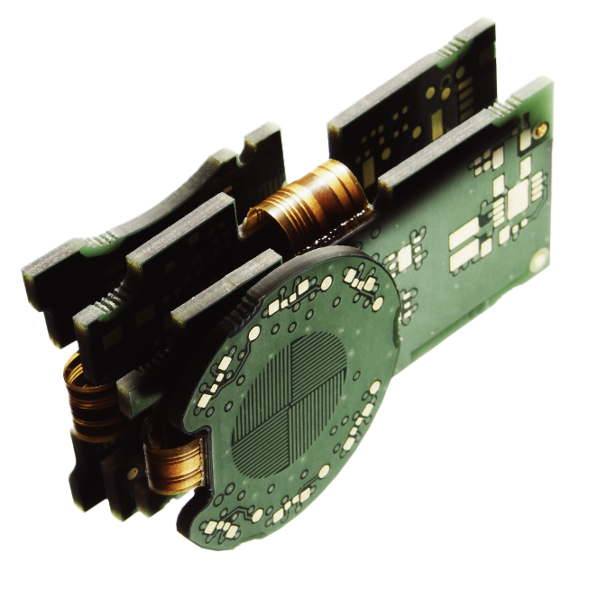
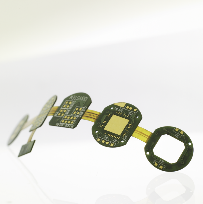
RIGID-FLEX printed circuit boards combine the benefits of flexible and stiff board technologies. These PCBs provide mechanism reliability in condensed packages of extreme conditions that may not be tolerable for connectors. Depending on the application, most rigid-flex boards have some layers of flexible circuit substrates linked to one or more rigid boards externally and/or internally. Flexible substrates are made in a constant state of flex and can be frequently bent into a flexed curve during the complete lifecycle of the product.

Where are RIGID-FLEX PCBs used?

RIGID-FLEX PCBs offer various applications, ranging from smart devices to cell phones and digital cameras. RIGID-FLEX board fabrication has been increasingly used in medical devices such as pacemakers for their space and weight reduction capabilities. These advantages, together with environmental survivability, make RIGID-FLEX the perfect system for aviation and military guidance systems, weapons, and satellites.

In consumer products, RIGID-FLEX does not just maximize space and weight but significantly improves reliability and improved signal integrity eliminating many needs for solder joints and delicate, fragile wiring prone to connection issues. These are just some examples, but RIGID-FLEX PCBs can be used to benefit nearly all advanced electrical applications, including testing equipment, tools, and automobiles.

RIGID-FLEX printed circuit boards are an excellent solution for assemblies that may be exposed to repeated shock or high vibration. Unlike Rigid Standard PCB, interconnected with cables, they will be reliable in an environment like this. The flex part also resist UV, radiation, harsh chemicals, and oils, ensuring a longer product lifecycle. Although Rigid Standard PCBs are thicker and stronger, RIGID-FLEX systems typically react to unfriendly environments like this more effectively – it may be why these systems are widely used in automotive electronics.

How are RIGID-FLEX PCBs made?

RIGID-FLEX board designs are more challenging to create than traditional rigid board designs because they are made in 3D space, which allows for higher spatial efficiency. Designers can twist, fold, and roll flexible board substrates to get their desired results by designing three dimensions.

In the early phases of designing, it is beneficial to carefully consider and thoroughly evaluate the available possibilities of RIGID-FLEX solutions that will yield considerable benefits. In addition, it’s vital to involve the PCB fabricator early in the design process to guarantee that the design and fabrication phases are in sync and that final product changes are considered.

The method has been proven and reliable in various applications, including stiff flex prototypes and large-scale PCB fabrication and PCB assembly. The flex PCB section excels in overcoming space and weight constraints with spatial degrees of freedom.

Minimized space

Addresses the consumer‘s needs by miniaturization in electronics – minimizing space by applying 3D wiring that can fold into minimal profiles.

Addressed consumer’s needs

Reduces product weight by eliminating additional parts, such as connectors and cables.

Greater reliability

Enhances the electrical performance of a product by reducing the need for solder joints – a homogeneous RIGID-FLEX unit is more reliable than one with separate PCBs and connectors.

Complete testing

It makes a complete test of the electronic possible and simplifies conditions for it – all the RIGID-FLEX components are accessible and may be tested before system assembly.

Increased productivity

Increases employees‘ productivity by making the PCB assembly process more straightforward. By eliminating additional single parts, RIGID-FLEX PCB reduces the time needed for assembly.

Controlled impedance

The interconnections between the rigid parts in a RIGID-FLEX solution, has higher signal integrity than same set up but with rigid PCB parts connected with cables. This makes design of controlled impedance signals easier and with higher reliability.

Types of Rigid-flex PCBs

According to the IPC-6013 classification, there is only one type of flex-rigid construction since it is a mix between common and rigid PCB and flexible layer/s to build the final function.

Type 4

  • Two or more conductive copper layers with either flexible or rigid insulation material as insulators between each layer
  • Plated through-holes extend through both rigid and flexible layers
  • Blind and buried vias available
  • Stiffener materials: polyimide, FR4, stainless steel, aluminum
  • Rigid materials: 180 TG FR4, low flow prepreg -High-speed controlled impedance in surface micro strip or stripline configurations

Capabilities

Feature

Capability

Number of Layers

1-8 layers

Build Time

3-5 days

Polyimide base material

Polyimide, PET, Polyester-Flex

FPC Thickness

0.08 mm - 0.4 mm

Min Track / Spacing

>=0.06 mm

Min Hole Size (diameter)

>=0.35 mm

Coverlay (Flex Part)

Yellow Coverlay, White Coverlay, Black Coverlay

Silkscreen Color

White,Black

Surface Finish

Immersion Gold, OSP, Immersion Silver, Immersioni Tin

Finished Copper

0.5 oz - 2 oz

All you need to know about Rigid-Flex PCB

Rigid-Flex

As its name sounds, the rigid-flex PCB is a mix of both rigid and flex PCBs, and features the great qualities of both while eliminating many of their individual limitations. A rigid-flex PCB includes flexible materials in conjunction with rigid materials by adding flexible circuit cores inside of the rigid circuit board materials, ultimately combining the versatility of flexible circuits with the stability, strength and circuit routing densities of rigid PCBs.

The ability to combine high density routing with the flexible interconnections together low weight and compact design. Together with the elimination of cables between devices, it also leads to better signal integrity of the interconnection.

Everyware where the environment needs compact design, high durability and reliability such as radar equipment, GPS, radio communication systems, control tower systems, noise and vibration testing systems, motion sensors, military and aerospace systems.

Explore our other products

Standard PCB

Our definition of “Standard PCB” is a rigid glass-fibre board with one or more layers.

HDI PCB

High-dense-interconnect PCBs meet the demand for smaller PCB with more compact components by increasing wiring capabilities.

Flexible PCB

Flexible printed circuit boards get the name from the ability to be bent in a working application.

Metal Core PCB

A metal core printed circuit board uses metal as its base material to spread heat accumulated due to some electronic components operating on the board throughout the board.

High-Frequency PCB

High-frequency PCBs are often needed while developing high-frequency products, such as satellite systems, radio frequency, microwave, mobile telephone base stations, etc.

Solder Paste Stencils

Customized high-precision laser-cut solder paste stencils are used by the subcontractor assembly company to apply solder paste with high accuracy to all places that shall be soldered.

Prototypes & Pilot Runs

PCB prototyping can be the most important step during electronic development.

Learn more how we ensure quality of our products.

Learn more

Capabilities

Feature Capability
Number of Layers 1-8 layers
Build Time 3-5 days
Polyimide base material Polyimide, PET, Polyester-Flex
FPC Thickness 0.08 mm - 0.4 mm
Min Track / Spacing >=0.06 mm
Min Hole Size (diameter) >=0.35 mm
Coverlay (Flex Part) Yellow Coverlay, White Coverlay, Black Coverlay
Silkscreen Color White,Black
Surface Finish Immersion Gold, OSP, Immersion Silver, Immersioni Tin
Finished Copper 0.5 oz - 2 oz

Contact sales

Let’s get this conversation started. Tell us a bit about yourself, and your needs. We will get back to you within few hours.

Get a quotation

    We will get back to you within few hours